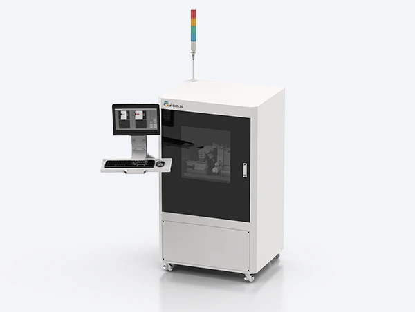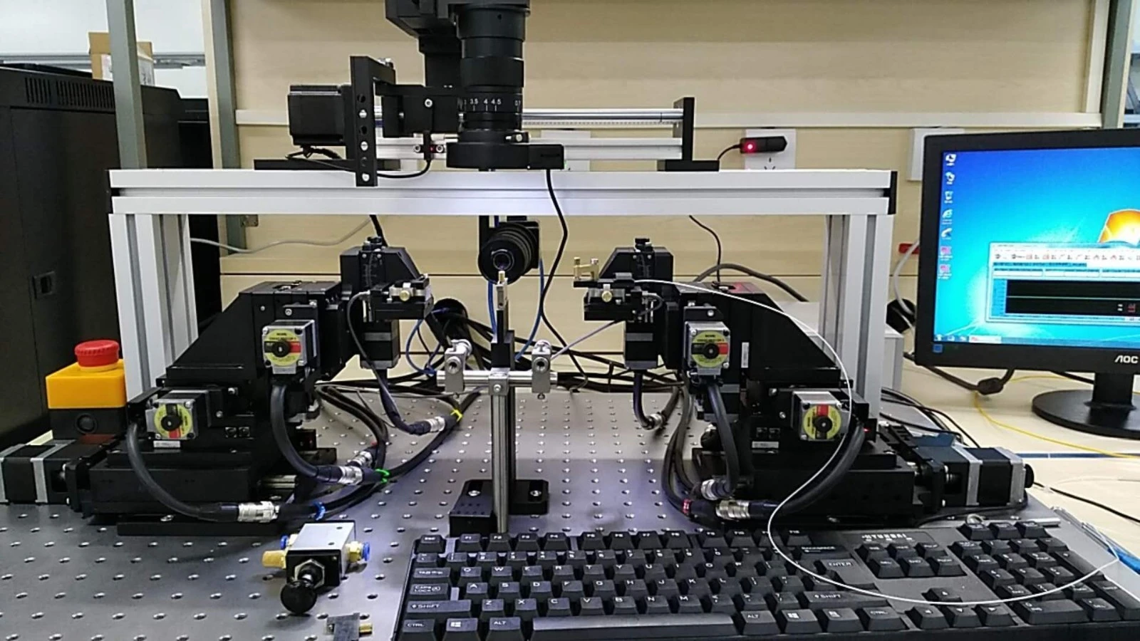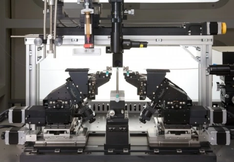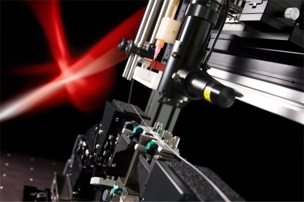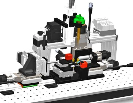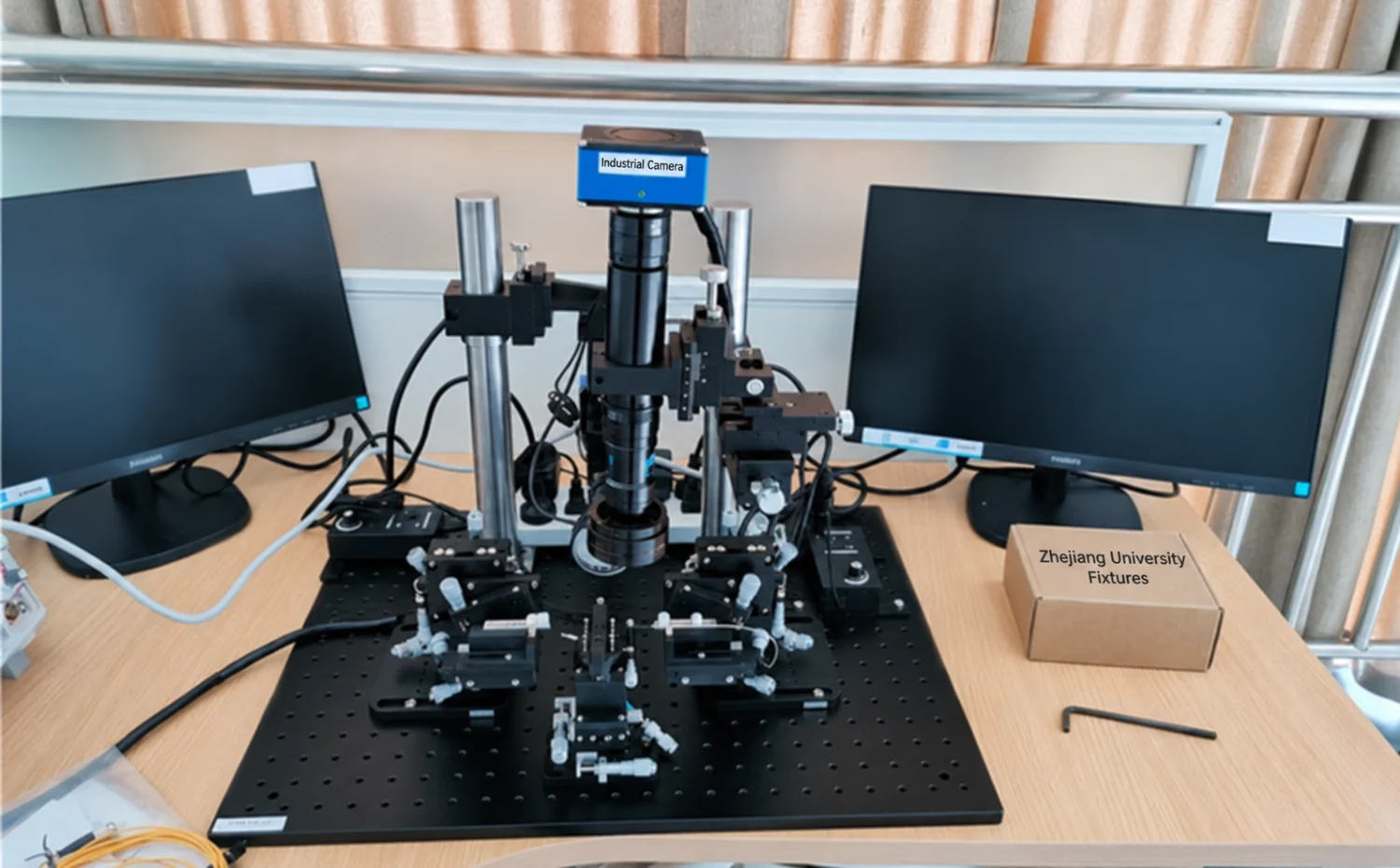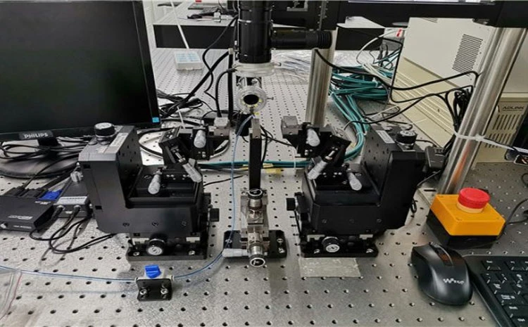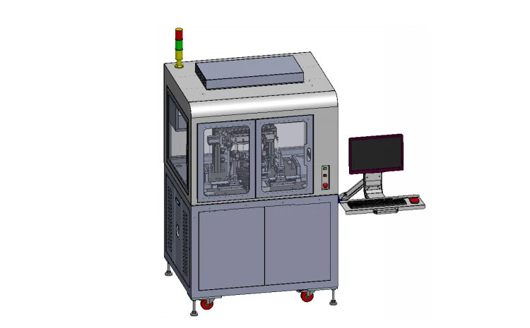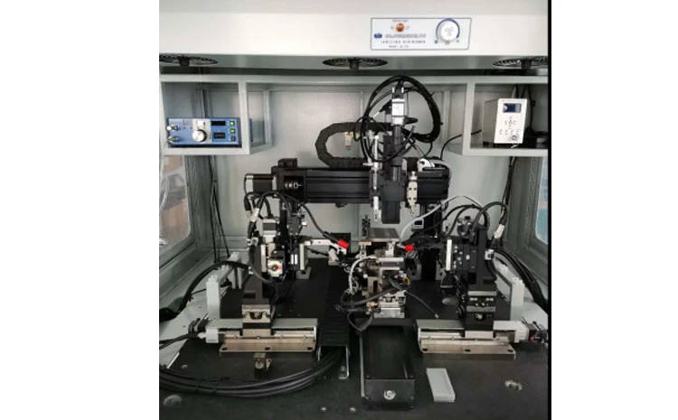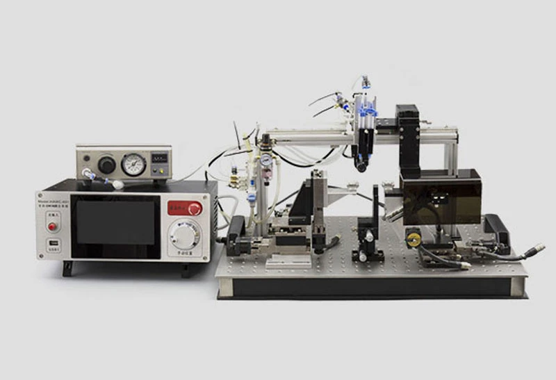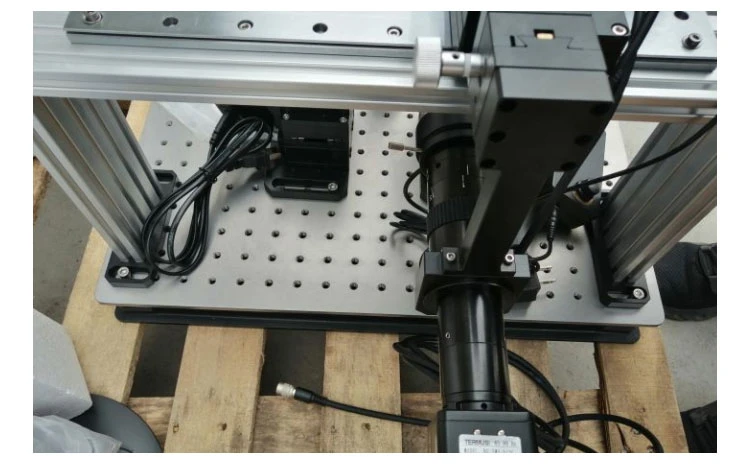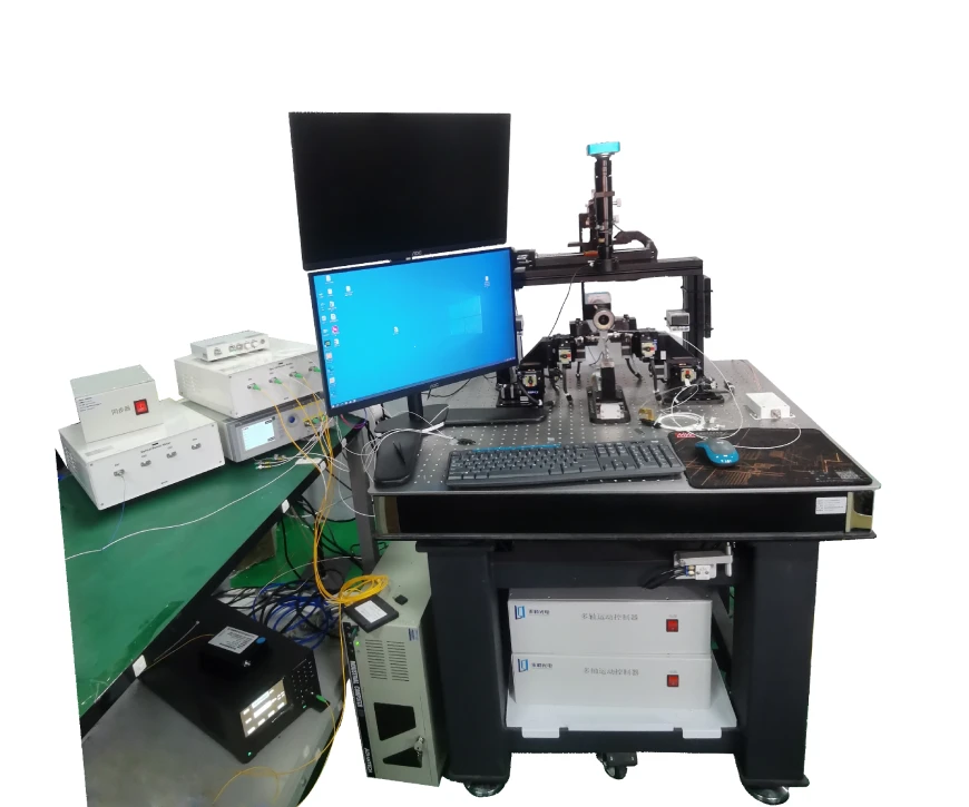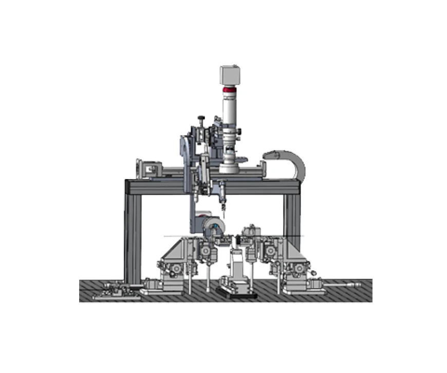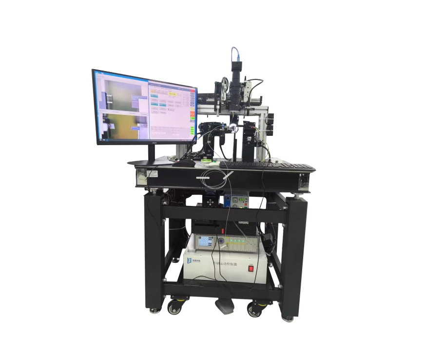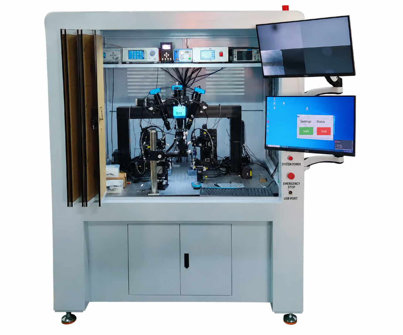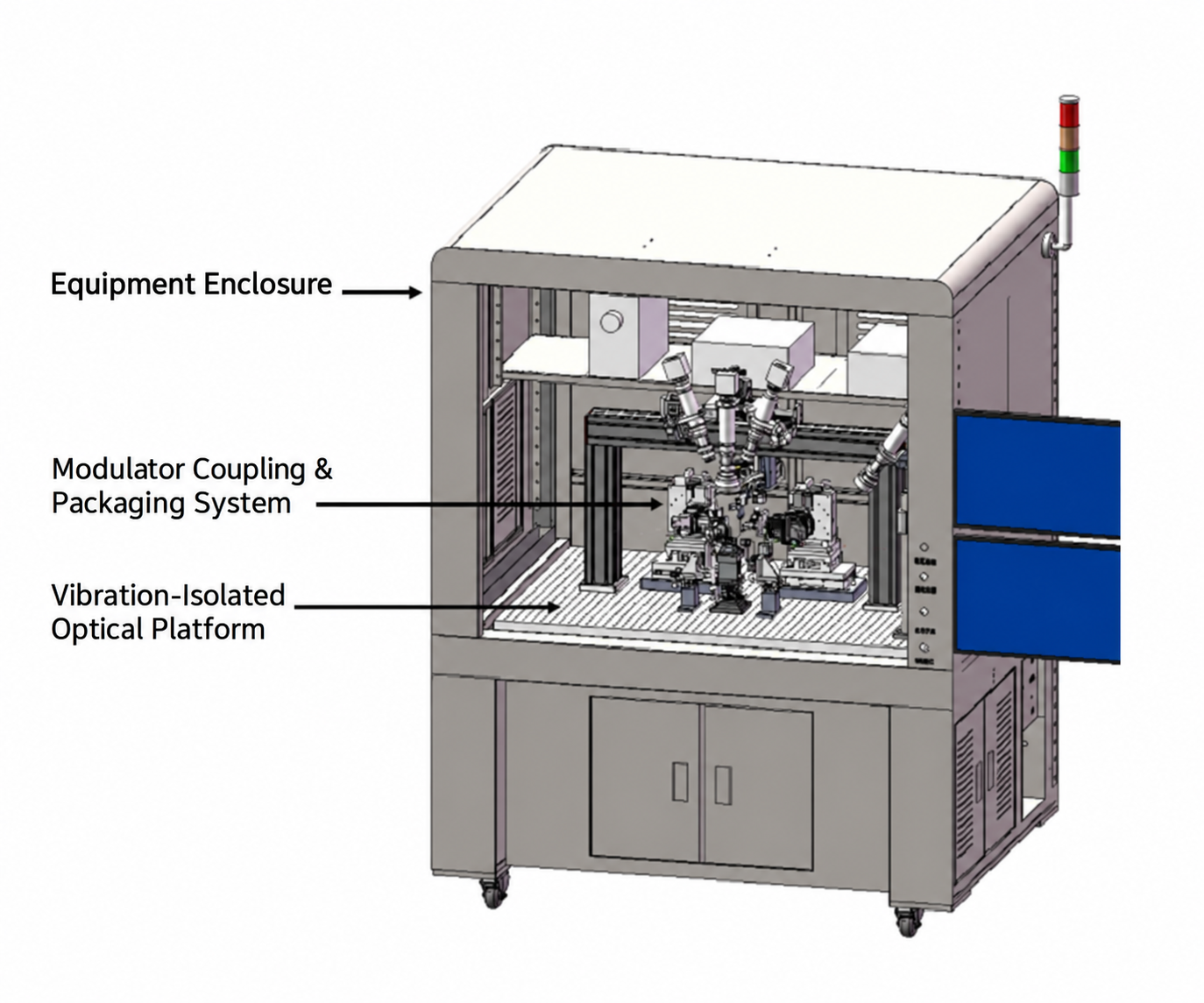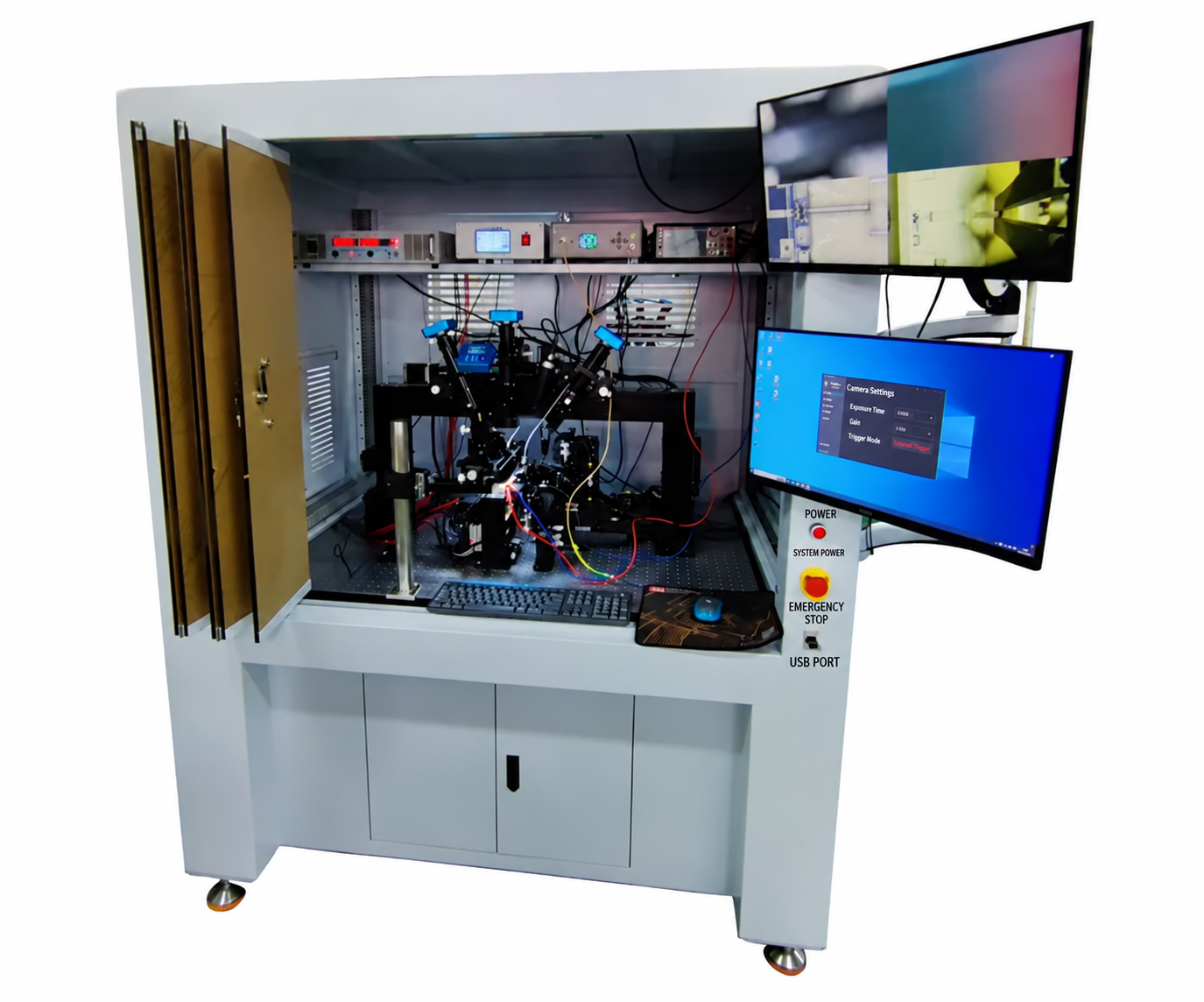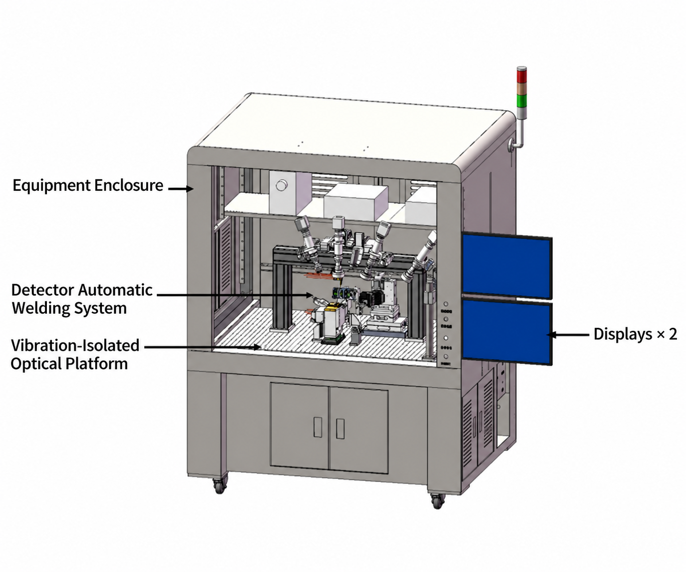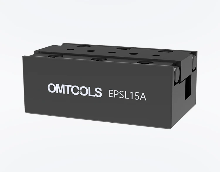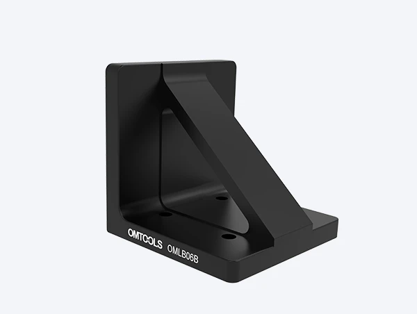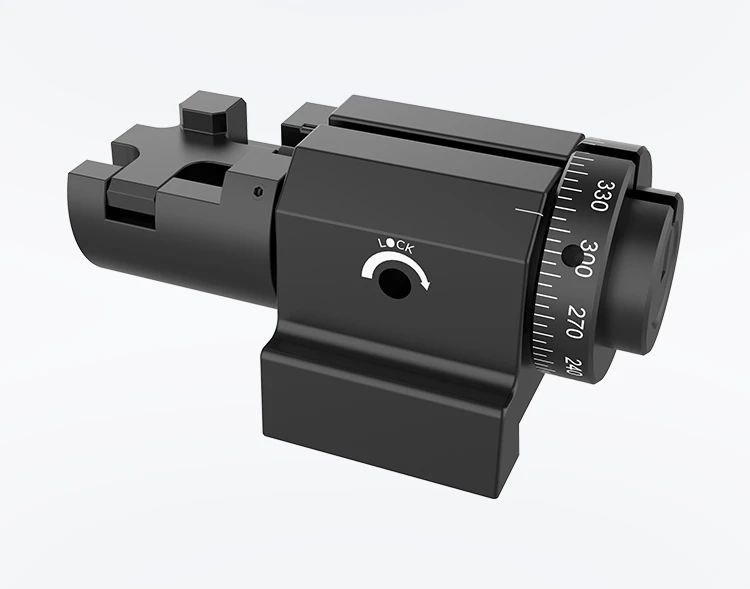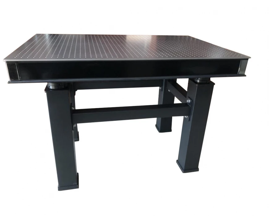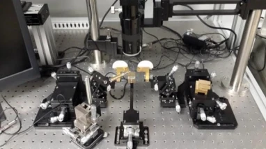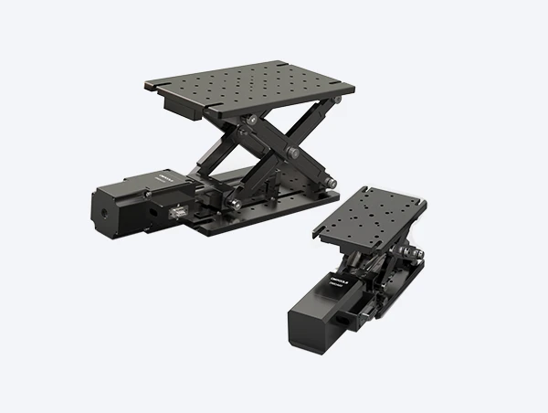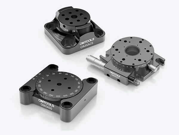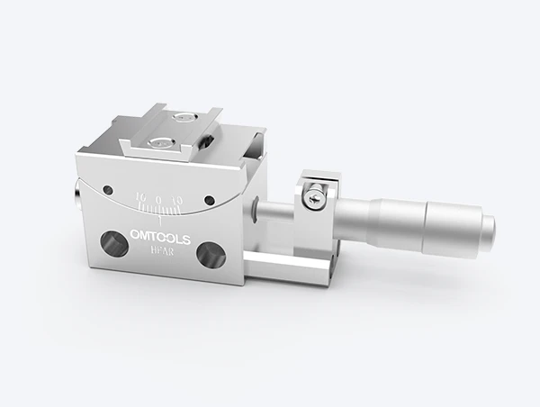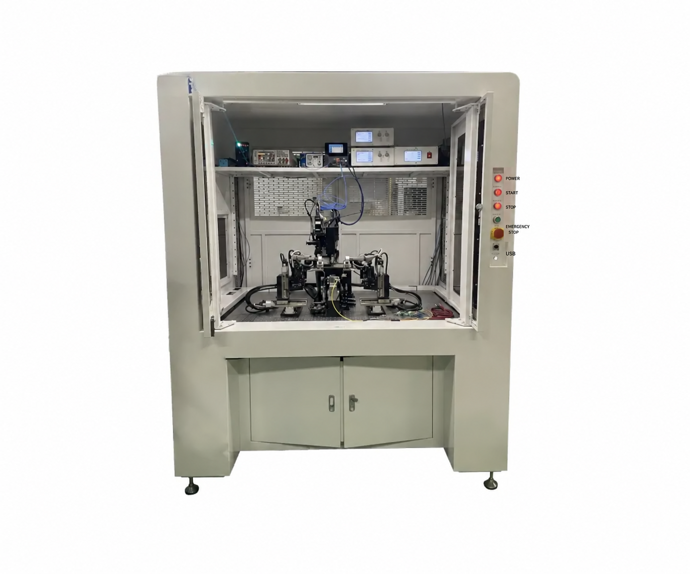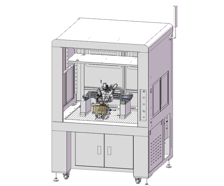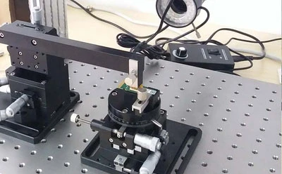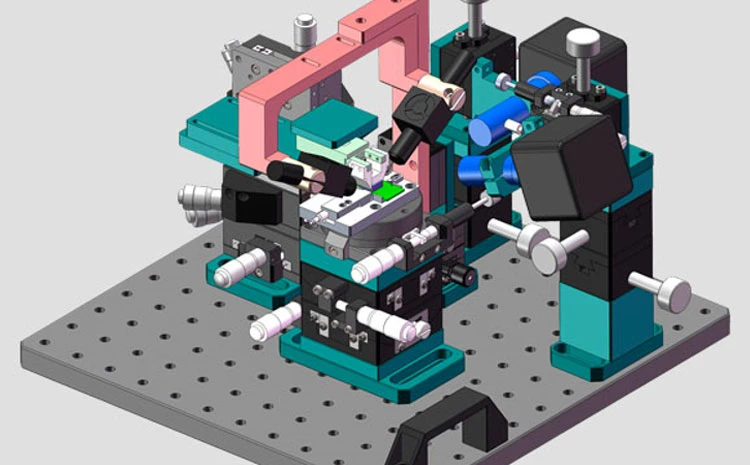
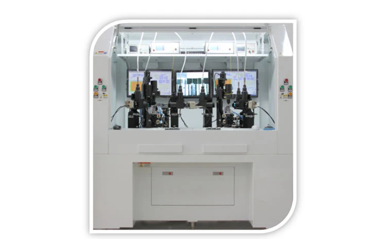
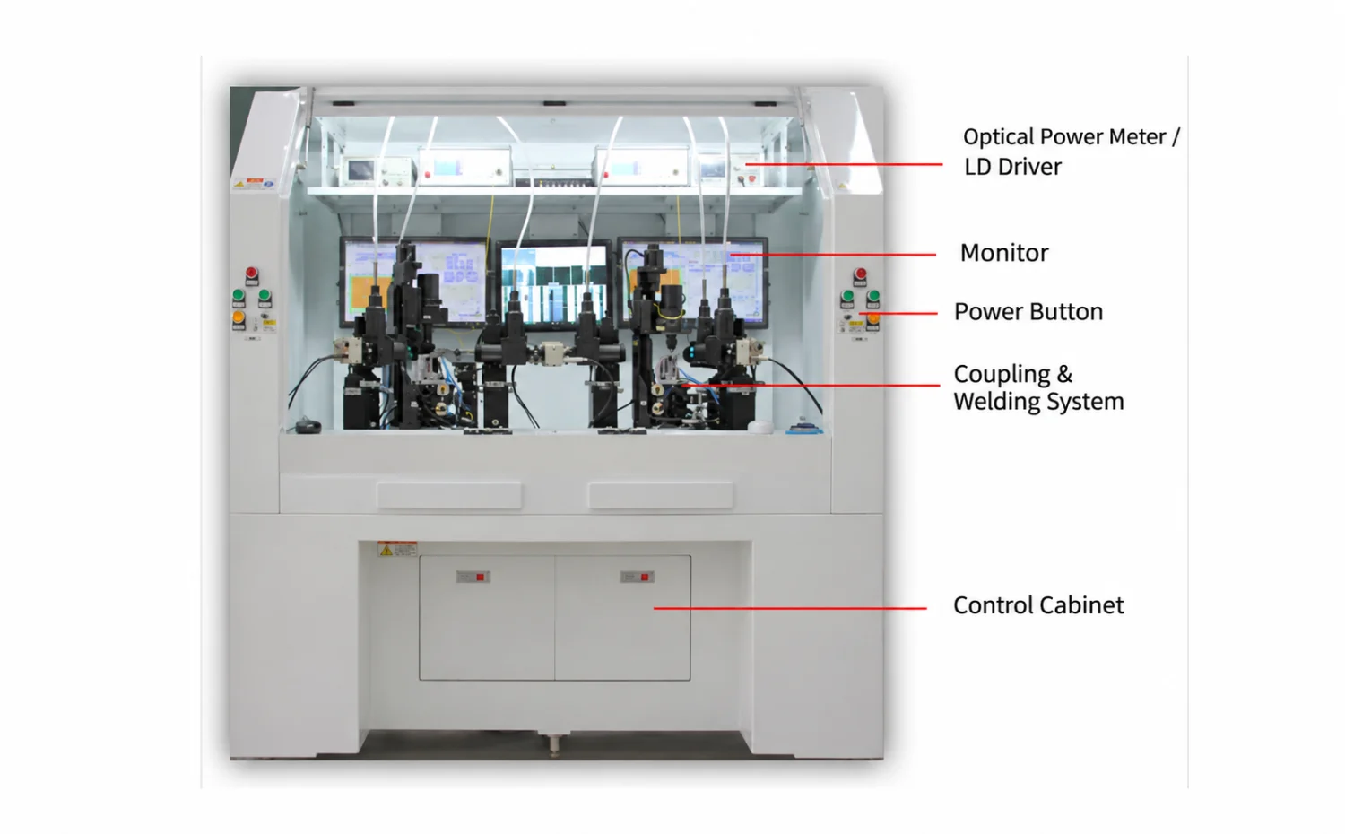
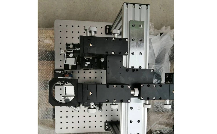

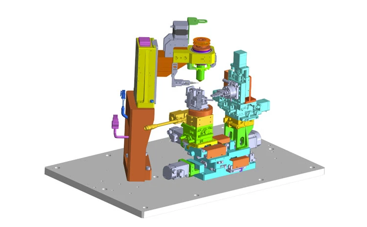
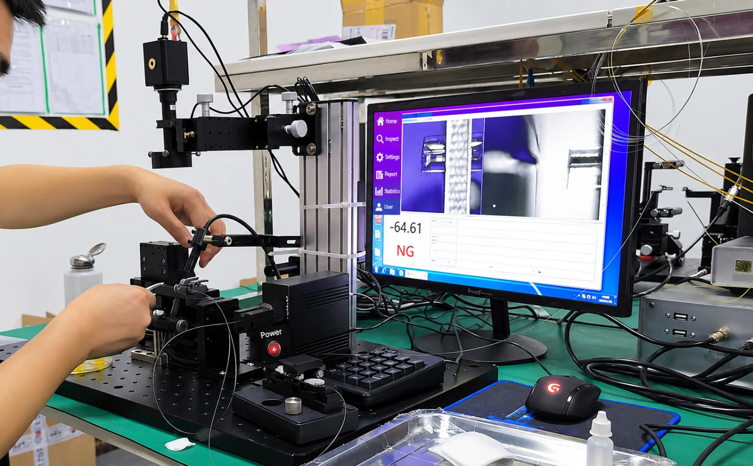
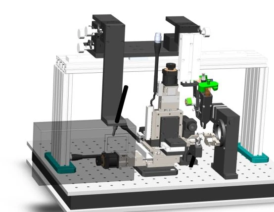
BOSA coupling system modular structure system: The modular architecture concept provides sufficient space for system modification and upgrade. Independent module distribution: Alignment coupling system, laser welding system, optical feedback system, optical drive system and other functional components are relatively independent, and the switching of different optical device packaging processes is flexible and convenient. Quick installation: The system is built on the optical platform base, which has good stability and can well resist external interference. The independence of each component makes installation of the system easy and fast. Auto-alignment: reliable search capabilities
BOSA coupling system
Automatic alignment:
Compared with manual alignment, which relies on operator skills and is highly uncertain, automatic search can stably and quickly find the maximum optical power point (the alignment target threshold interval can also be adjusted through the program).
★Innovative clamp design: stable clamping and various models
We provide chucks suitable for different types and sizes of devices and can be customized according to customers' production requirements.
★Chinese interface, providing process program development
l Simple initialization process;
l Optimized automatic light seeking control algorithm;
l Connect to the database and complete program switching of different types of devices by importing data.
★System configuration can be customized: provide customers with the most cost-effective products
DY-LW-I: It adopts five-dimensional fully automatic alignment + large rotating platform welding method. The coupling is accurate and fast, and the solder points are evenly distributed. It is suitable for ordinary two-body devices and simple three-body pigtail devices.
DY-LW-II: It adopts six-dimensional fully automatic alignment + large rotating platform welding method. Based on the I type, it adds pin (adapter) angular rotation movement. It is suitable for two-body devices or three-body pigtail devices that require higher device performance.
DY-LW-III: It adopts six-dimensional fully automatic alignment + large rotating platform welding method, and is mainly developed for three-body high-performance pigtail devices. On the basis of type II, the isolator rotation function is added, which can accurately search and align the angle of the isolator. It is suitable for three-body pigtail devices that require higher device performance.
Automatic alignment, welding, one-click operation
1. Real-time online monitoring of optical power
2. Diversified fixtures adapted to various devices
3. Software suitable for various types of devices
4. Modular structure system
5. Can be customized according to user needs
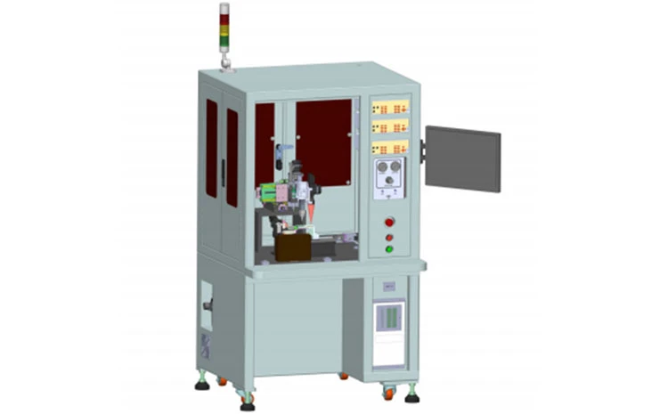
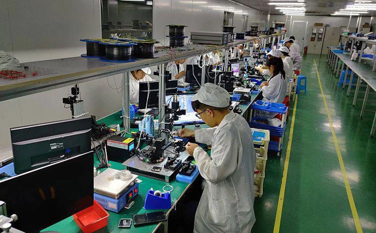
The DY-LW series machine adopts a double-station layout, with one operator responsible for two stations, resulting in high production efficiency. The equipment has stable performance, compact structure and small footprint. At the same time, the equipment supports a variety of YAG laser welders, and users can choose to configure them independently.
The standard operating time of a single station of the equipment: <50s for ordinary two-piece devices and <90s for pigtail devices.
Main specifications
|
model |
DY-LW-I/DY-LW-II/DY-LW-III |
|
Number of motion axes |
15Axis/16 axis/16 axis (based on single station) |
|
power supply |
AC 220V |
|
Air pressure source |
0.3~0.7MPa |
|
Laser output head distribution |
3Towards120Spend |
|
Laser head welding angle |
0flat welding/15bias welding |
|
Vision CCD |
Coaxial with laser emission |
|
Supported product types |
|
|
Overall dimensions |
1500(W)x1000(D)x1700(H) |
Circore coupling operation process in BOSA
1 Turn on the power meter, ASE light source, point light source and UV point light source.
2. Observe whether the Circore coupling clamp is complete. You can lightly touch the joints of the clamp to see if there are any abnormalities or looseness, and clean the Circore placement platform.
3. Use a photosensitive card and a ruler to calibrate the light emission direction of collimator 1 to ensure that the horizontal direction is parallel to the optical table surface and the vertical direction is parallel to the side of the optical table.
4. By switching the light on, use the power meter probe 2 to measure the ASE light source power P0 and the point light source power P0‘ respectively, and record the values.
5. Place the clean product with the rotating piece glued on it on the four-dimensional adjustment frame platform, so that both sides and bottom of the product are close to the positioning benchmark, and then press the product from above (touch the product with tweezers without shaking).
6. Adjust the X and Y directions of the collimator 1 so that the light passes through the PBS block of the product (at this time, a haloed spot appears on the photosensitive card in both the transmission and reflection directions of the product).
7. Place a magnet on the rotating piece of the product to make it reflective. Under the ASE light source, use the power meter probe 2 to collect the reflected light P reflection, fine-tune the X and Y directions of the collimator 1 so that the P reflection reaches the maximum value, and record the value.
8. Flip the magnet and use the power meter probe 2 to collect the transmitted light P and record the value.
9 Make sure IL1=P-transparent-P-reflective <0.35dB. This can determine that the direction of our Nano PBS is correct.
10 Ensure that the position of power meter probe 2 remains unchanged, flip the magnet so that it is in the reflection state, record the power P separation at this time, and calculate P transmission-P separation ≥ 21dB, indicating that the isolation of the product is qualified.
11 Adjust MoticCAD to make the reflected light round and brighter on display 1, and the light spot is at the center of the imaging circle of display 1.
12 Place the clean 5/4 wave plate with capillary tubes glued on it into the V-shaped groove of the six-dimensional adjustment frame, rotate the 5/4 wave plate as much as possible to ensure that the side of the 5/4 wave plate is parallel or perpendicular to the optical table surface, and press the 5/4 wave plate tightly.
13. Adjust the X, Y, and Z directions in the six-dimensional adjustment frame so that the 5/4 wave plate is 0.1~0.5mm away from the PBS block and at its center. Place the photosensitive card in a place with reflected light, and adjust the two arc swing knobs on the six-dimensional adjustment frame so that the two light spots on the photosensitive card overlap.
Remove the photosensitive card and observe the spot 1 of the monitor, and fine-tune the arc swing knob to make the two spots overlap. Use the power meter probe 2 to collect the reflected light power P1, fine-tune the X, Y and 5/4 wave plate axial rotation knobs in the six-dimensional adjustment frame in three directions to maximize P1, record the value, switch to the point light source and record the value P1', and then switch to the ASE light source.
14. Adjust the Z-axis of the six-dimensional adjustment frame to withdraw the 5/4 wave plate, and use a dispensing needle to double-cure glue on the center point of the 5/4 wave plate. Then adjust the Z-axis of the six-dimensional adjustment frame to push the 5/4 wave plate to the PBS block, and observe the display 2 at the same time. When the double curing glue contacts the PBS block and completely spreads on the 5/4 wave plate, it immediately stops moving. Observe whether the two light spots on display 1 completely overlap. If they do not overlap, fine-tune the two arc swing knobs to make the two light spots completely overlap again. Then adjust the fine-tuning knob on the Z-axis of the six-dimensional adjustment frame to allow the 5/4 wave plate to slowly move toward the PBS block while observing the light spot on display 1. When the light spot of display 1 begins to move, it immediately stops and fine-tunes in the opposite direction until the light spot returns to a completely overlapping state. Use power meter probe 2 to collect the reflected light power P2 at this time and record the value. Switch to the point light source and record the value P2', then switch to the ASE light source.
15. Move the collimator 2 to the reflected light position, adjust the optical power P3 received by the collimator 2 to reach the maximum value, and record the value.
Switch to point light source and record value P3‘. The requirements of P0-P3<1.2dB, P2-P3<0.8dB (P0‘-P3‘<1.2dB, P2‘-P3‘<0.8dB) are met under both light sources.
16. If P3 and P3' meet the requirements at the same time, perform UV curing on the 5/4 wave plate, and observe that the power value of P3 decreases at the same time and must be less than
0.1dB. If the drop is greater than 0.1dB, stop curing immediately and wait until the value recovers before curing. The curing time is 3 to 5 minutes. 17. Gently loosen the 5/4 wave plate with one hand and observe that the change in P3 power value must be less than 0.1dB. Move the 5/4 wave plate to the side, adjust the six-dimensional adjustment frame to move downward by more than 1mm, and then rotate the Z-axis to move backward and completely away from the capillary tube. Make a mark on the magnet, loosen and tighten it, and place the product on the hot plate to cure at 150°C for 30 minutes. Remove the product from the hot plate, separate the magnet from the product, and clean it. Pay attention to the logo and apply 353ND glue on the bottom of the magnet. Place the magnet back on the rotating piece, then place it on the hot plate to cure at 150°C for 1 minute. Remove it, clean it again, and put the product into the self-adsorption box. At this point, the Circore coupling step is completed and can be transferred to the next process.
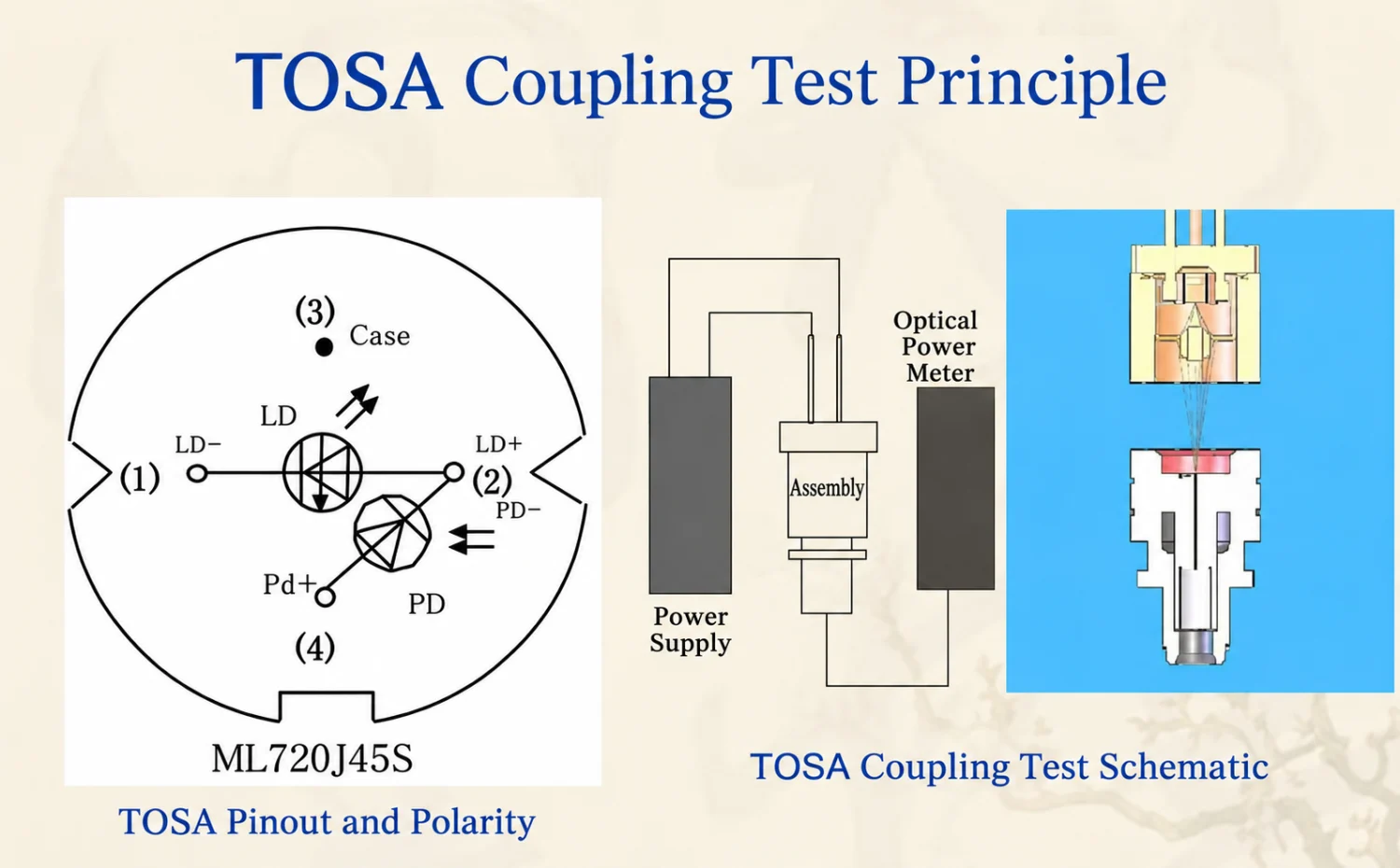
At present, many devices in optical fiber communications have couplings. The principle is to transmit the light emitted by the light source to the photosensitive surface of the photosensitive element through the optical fiber, and use precise alignment to align the light with the photosensitive surface, so that the light energy can be received by the photosensitive surface to the maximum extent, and the noise of the light energy can minimize the bit error rate of the optical transmission signal.
Therefore, the coupling position often affects the reliability and various indicators during the optical transmission process. Therefore, there must be a coupling process in the production process of communication devices such as BOSA.
How to operate the BOSA receiving coupling automatic station
Production experience, focusing on automatic or manual light alignment systems for various waveguide chips and test instruments for optical passive devices or active devices. Provide complete production and testing equipment. Customize simple, practical and standard test systems according to customers.
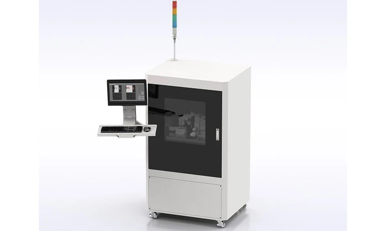
The dual-station design of automatic coupling equipment is suitable for TX/RX various TOSA, BOSA, ROSA and CPON product glue process devices. It supports different wavelengths of light sources such as 850, 1270, 1310, 1490, 1550; automatic coupling, automatic dispensing, automatic irradiation, independent power-on light source, monitoring return loss system, and CCD monitoring. Single station system is independent. The left and right machine positions can be combined. When one machine position is loading materials, the other machine position is running, and the equipment utilization rate is high.
<!–